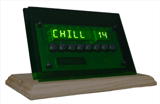
I built an alphanumeric LED display that connects via USB to my PC and can display RSS feeds, the weather (like wind chill, above), the time, or just about anything.
When I built my Homemade Digital Clock, I shamelessly overdesigned it. It had an eight character alphanumeric display (plus two discrete LEDs for a colon), four more discrete LEDs for indicators, two printed circuit boards, and two microcontrollers (three, if you count the GPS it uses as its time source), one of which was running at 20MHz. That’s more processing power than the Apollo spacecraft had on board! All for a stupid clock!
I had a few reasons for this. First was that I had the idea that I might re-use the display for other things in the future. Second was that when all you have is hammer, everything looks like a nail. I’m a software engineer by trade, so my first thought is always to use a programmable microcontroller to solve a problem. I’m so bad that if I needed a square wave, I’d more likely use an 8 pin microcontroller than a 555 chip.

Anyway, when I had my clock’s printed circuit boards made, I had them make several. Now, I’ve added a USB port to one of them, connected it to my PC, and written a program in C# to control it. It can fetch data from local files or the web, extract specific pieces of data, format them and display them on the LEDs. The user can enter C# expressions that evaluate to true or false and cause the discrete LEDs to light up (and even flash). The user can also configure alarm sounds and actions to take when the front panel buttons are pressed.
I’m making my schematic, board layout, and software available for free here. The UI is definitely for techies only, but it could probably be adapted to other PC-controlled displays like those from Crystalfontz and Matrix Orbital.
Here’s a short introduction to the display’s capabilities and UI (if you’re wondering what the computer is in the background, it’s a modern PC in a small form-factor Altair 8800 replica case):
And if you’re considering downloading and playing with the UI, here’s a much more detailed description of it:
Finally, here’s the schematic and layout (readable by the open source program Kicad), the PIC 18F4550 firmware (readable by Microchip’s MPLAB and using their free C18 compiler), and the PC UI (readable by Microsoft’s free Visual C# Express):
Update: here are images of the schematic and the (double sided) PCB layout. Click on the images to enlarge:


Could you post pictures of the schematic and board please. It would help a lot.
Done! Enjoy.
– Bob
Thanks!
does this work on PIC18f4580
Hi Matt,
The 18F4580 doesn’t have a USB peripheral, so the short answer is no. The longer answer is yes: the chip’s UART connection is brought out to pins on the board, so you could modify my code to get commands from the UART, and talk to the board that way. In fact, that’s what I did in my digital clock.
thank you
hey this is great piece of work there sir . i also own a free educational site based on projects ! well give it a look and i will apriciate your review or comments thanks !
fahim
http://www.projectpiles.com