I’m building a homebrew CPU based on microcode. I made a microcode compiler in Google Sheets. It can easily adapted for other people’s microcoding needs.
What is microcode?
You can find an in-depth explanation of microcode on (of course) Wikipedia.
But briefly, a CPU’s microcode is implemented in ROM (in my case, EEPROM). It contains the steps required to execute the CPU’s instructions. The ROMs’ address pins are the state of execution, e.g. the op code of the current instruction, a cycle counter, interrupt request signal, the condition codes (Carry, Negative, Overflow, Zero), and any other signals that affect how an instruction executes.
The ROMs’ data lines are wired to parts of the CPU that need to be enabled for execution of the instructions. An instruction to add two registers, for example, needs to enable the register memory for reads, tell the ALU to do an add, enable latches to store the condition code results, and enable buffers to direct the ALU’s output to its destination.
Typically, microcode controls a lot of signals. My design will need 24 to 32 signals, so I’ll need 3 or 4 eight-bit-wide EEPROMs to implement the microcode. It’s not uncommon for CPUs to have hundreds of signals.
Overview
And so I made a spreadsheet to help me write the microcode. The leftmost columns are the state of execution. The rightmost columns are the signals to enable gates, buffers, etc.
I wrote an app script that compiles the spreadsheet into files that can be burned into ROMs, or read into a Verilog program if you’re implementing the CPU in an FPGA.
This should be adaptable to other homebrew CPUs that use microcode. You would need to remove my microcode programming and write your own, of course. But the compiler is universal.
You can see a read-only version of the spreadsheet here. Note that this does not include the necessary compiler script (more about that later).
Details
The spreadsheet has three pages and a script.
The first page is Settings:
(Click to enlarge in a new tab.)
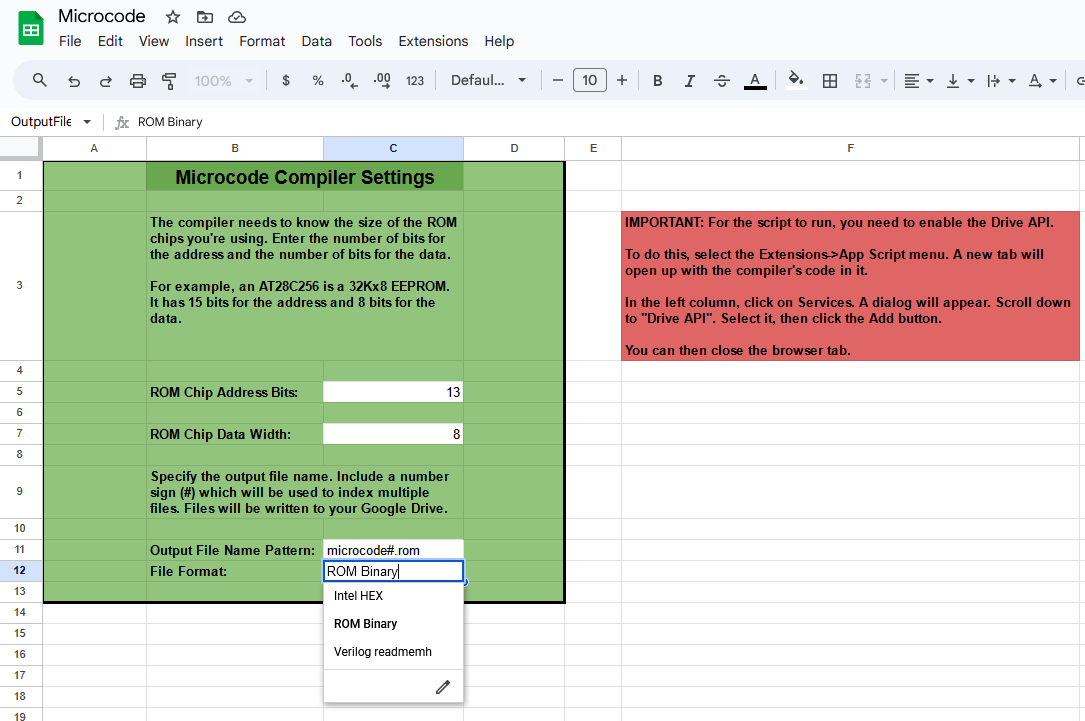
Here, you specify the size of the ROM chips you’re using and the type of output you want. You specify the number of address bits the ROM has (e.g. an 8Kx8 ROM has 13 address bits), the number of data bits (usually 8), the output file pattern (e.g. “microcode#.rom” will cause the compiler to generate files with names microcode1.rom, microcode2.rom, etc.), and a choice of output file format: ROM binary (i.e. for an 8Kx8 ROM, the file will be 8K bytes), Intel HEX format, or Verilog readmemh format (i.e. the file is readable by Verilog’s readmemh() function).
(If you’re interested in Verilog, check out the KiCad-to-Verilog converter I wrote.)
The compiler will generate as many files as it needs to hold the microcode you’ve programmed. Since this is a Google Sheet, the files will be generated in the root of your Google Drive.
There’s a big red box on the Settings page, screaming for your attention. It explains how to authorize the compiler script to access your Google Drive before the first time you compile.
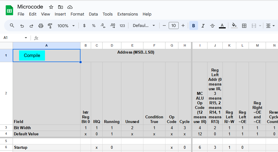
The second page is the microcode:
(Click to enlarge in a new tab.)
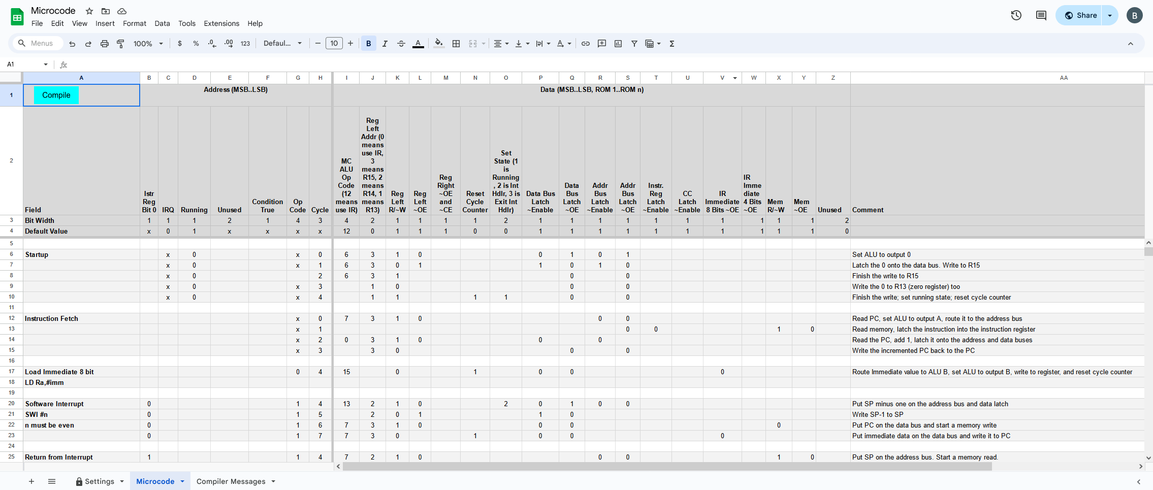
The left columns are frozen (in a spreadsheet’s sense of freezing columns so that they don’t scroll off the screen). This is important: the compiler script uses the frozen columns as the ROMs’ address lines and the unfrozen columns as the data in the ROMs.
Column A is not processed by the compiler at all. It’s there for writing human-friendly comments. I use it to describe when rows of microcode get executed, e.g. during startup, or which executing the instruction to load a register with an immediate value, etc.
The top rows are also frozen. The compiler processes the rows labeled “Bit Width” and “Default Value”, but ignores any others. I use the upper rows, again, for comments reminding me of the bit order.
The Bit Width cells specify the width of a field. For example, in my architecture, the op code is 4 bits. So the Op Code column has a bit width of 4; instructions can use at most 8 cycles to execute, so my Cycle column has a bit width of 3. Many signals, like the Output Enable line for the left side of the dual port memory that’s holding the registers, are just 1 bit wide.
Every column has a default value. If a cell in that column is left empty, the column’s default value is used. For example, the Output Enable line for the register is usually 1 (high) (OE signals are usually active low). So for all the microcode instructions where I’m not doing anything with the register, I can just leave that cell blank. The compiler will fill in the default value, 1. This makes it easier to fill out the spreadsheet and makes it much easier to read: only the filled-in cells are doing something important.
In the leftmost columns, where the ROMs’ address bits are being specified, the default value (or even the value in a cell) can be x, which means “don’t care”. For example, when the CPU is executing the microcode to load the next instruction, it doesn’t care what the op code is (any op code appearing on the ROM’s address lines would be from the previously executed instruction). So we set the Op Code cell to x. The compiler will generate multiple copies of this microcode row, placing them at address locations where the Op Code bits are 0, 1, 2, … 15.
Notice how an instruction fetch is done, starting at row 12. there are four lines of microcode, corresponding to cycles 0, 1, 2, and 3. Then, if you look at the microcode for the Load Immediate instruction, starting in row 17, it specifies cycle #4.
So cycles 0 through 3 load an instruction, regardless of what value the Op Code address lines have. Once an instruction is loaded, the Op Code address lines become important. From cycle 4 onward, the microcode for the specific instruction gets executed.
The far right column is labeled “Comment”. More importantly, the Bit Width cell in that column is blank. A blank in the Bit Width cell tells the compiler to stop processing columns: no column to the right of that will be processed. And so any comments you care to write can appear there. I include comments describing what each line of microcode is doing.
Blank rows can be inserted anywhere. I use them to separate the microcode for each instruction. The shading of the rows has no significance to the compiler; I just added that manually as I wrote the microcode.
When the microcode is ready to compile, click the green Compile button in the top left cell. Google Sheets will display a message “Running script”. When it’s done, the third page of the spreadsheet will automatically be displayed.
The third page is the compiler output messages:
(Click to enlarge in a new tab.)
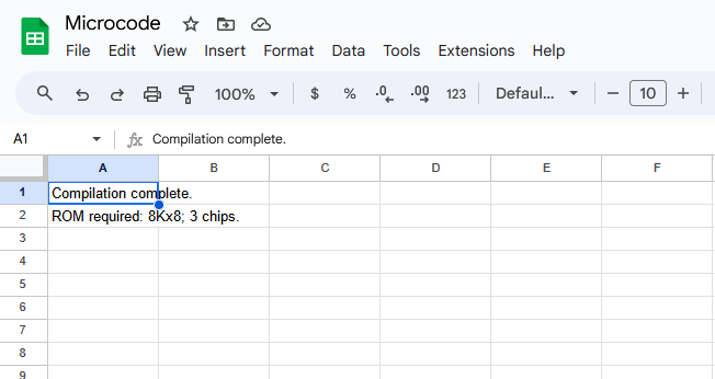
If all goes well, it will say compilation is complete and tell you how many files it created (one for each ROM chip). Otherwise, there will be a list of errors and/or warnings. A common warning is that an address location in the microcode is being written by two rows in the spreadsheet, e.g. if the left columns of multiple rows (especially with their “don’t care” values) resolve to the same address.
If files were generated, you’ll find them in the root directory of your Google Drive. Check the timestamps, though: it might take a little time for Google to synchronize the drive in the cloud with the files on your PC. More than once, I have compiled the microcode, then quickly burned EEPROMs from my local copies, only to realize I was using an old version of the files!
The script:
If you pull down the Extensions menu and select Apps Script, you get the secret sauce behind it all:
(Click to see entire program.)
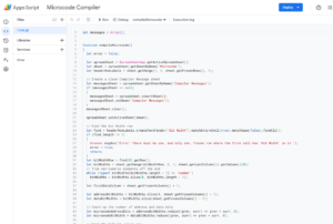
The compiler first reads the headers and figures out the widths of each field and their default values. Then, it goes through each row of the sheet, builds a string of 1s and 0s for all the data fields and splits it up into into bytes (or words, if the ROM chips are wider than 8 bits). Then it puts those byte values into the correct address locations in arrays for each ROM chip.
The compiling is done entirely in memory. When all the rows have been processed, the compiler writes out the files in the requested format.
How to get it for yourself:
To get the spreadsheet, use this link to make a copy in your own Google account.
Pull down the Extensions menu and select Apps Script. A new tab full of lovely Javascript (and even a few comments!) should appear. Feel free to peruse the code.
Test whether it works: follow the instructions in the red box on the spreadsheet’s Settings page, then go to the Microcode page and click Compile in cell A1. The first time you do this, Google will impugn my honor, warn you that the code has not been verified by Google, and plead with you to change your mind about running it. Remember, I said “feel free to peruse the code”.
If you choose to proceed, it will run, then switch you to the Compiler Messages page. Three files should be created in your Google Drive.
To adapt it to a different homebrew CPU, start with the Settings page. Set the number of address and data bits per ROM chip to match the chips you’re using.
Next, go to the Microcode page and delete the unfrozen cells of the Microcode page. Modify the frozen rows by defining your own design’s address and data bits. You might need to add or remove columns to match your design’s needs. Then write your own microcode program, compile, and burn the microcode ROMs.
I guarantee your microcode will work the first time, or your money back!