I wanted to switch to a microcontroller that I could program in C++, prototype with on a breadboard, had every peripheral I would ever need (including USB), would cost less than $10, and would keep working even after I hacked it to pieces. The result is the Black Knight board.
I’ve been using 8 bit PIC 18 microcontrollers for my projects so far. I like that they’re available in DIPs (so prototyping is easy) they range from a nice small 18 pins to 40 pins, they support the major I/O interfaces including USB, and they’re dirt cheap (a few dollars each). But I really hate programming in C, and this is a hobby that’s supposed to be fun. So I needed to move to a platform I could program in C++ without losing the other benefits.

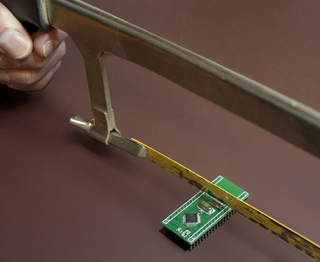
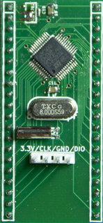
I ended up building the Black Knight board, based on ST Microelectronics’ STM32 ARM chips. I can produce one for less than $10 each (in quantities of 10, including the PCB and the components; high end versions of the STM32 might boost the price over $10). The unique thing about the board is that you can physically cut off pieces of it to remove the features you don’t need, and thus whittle it down from 40 pins to a minimum of 20. Yes, just take a hacksaw and cut off one end of the board. Since it keeps working after you’ve cut off its “limbs”, I’ve named it after the Black Knight in Monty Python and the Holy Grail.
Cut down to 20 pins, the features of the board are:
- 32 bit ARM at up to 72 MHz on its internal oscillator, 128K flash and 20K RAM.
- Power supply from 2V to 16V
- 17 I/O pins, all with optional pull up or pull down resistors
- Up to 2 USARTs, 2 IrDA (Infra-red), 2 SPI, 1 I²C, 3 A/D converters, and 6 PWM
- An SWD interface for programming and debugging the chip
- All but two of the I/O pins are 5V-tolerant.
That’s in a 20 pin DIP, programmable in C++, and less than $10. Not bad, huh?
If you want more, cut the Black Knight down to 24 pins instead of 20. You’ll get:
- Room for an external oscillator
- A USB port
- 4 more I/O pins (not 5V-tolerant)
- 2 more A/D converters and 2 more PWM
Keep 28 pins, and you gain:
- Room for a 32.767 kHz crystal for the STM32’s real time clock
- A pin for the clock’s backup battery
- 3 more I/O pins
- Another SPI, 2 A/D, and 2 PWM
With 32 pins, add:
- A 4 pin connector for the SWIM programming/debugging port (this is redundant with the SWD you have in the 20 pin DIP, but it’s more convenient for connecting an ST-Link programmer)
- 4 more I/O pins, including A/D and PWM functions
- Another USART and IrDA
Finally, with all 40 pins, you get still more I/O and peripheral devices.
| [portfolio_slideshow include=”329,328,327″ autoplay=”true” pagerpos=”disabled” navpos=disabled timeout=1250 align=right] |
The power scheme is interesting. As I mentioned earlier, the Black Knight can take anywhere from 2 to 16 volts. The STM32 µC accepts 2 to 3.6 volts. In the slide show to the right, you’ll see how I do it. I’ve laid out room on the board for a voltage regulator. Two of the pads, the voltage in and the voltage out, are oversized. If your external power supply is between 2V and 3.6V, just put a solder bridge across those pads. Otherwise, put in a voltage regulator in an SOT-89 package (I use the Microchip MCP-1703 chips). I ran into one problem: the MCP-1703s have an exposed conductor on the bottom of the package – something I didn’t know when I designed the printed circuit board. This could cause a short between the two oversized pads. I solved it by putting a small piece of paper on top of the oversize pads. If and when I revise the Black Knight board, I’ll need to redesign this footprint.
Naturally, some sacrifices needed to be made for all this. The biggest is the use of surface-mount parts. I have newfound confidence in my ability to work with them, but it’s still a challenge to work with the microcontroller’s 48 pin LQFP package. Positioning it and soldering it is fairly easy; cleaning up the solder bridges is a pain. In comparison, soldering the capacitors and resistors is a cakewalk.
I should mention that although the Black Knight is a DIP board with 0.1″ pin spacing, it is wider than the standard 40 pin DIP package. Its footprint is 0.8″ wide instead of 0.6″. So it won’t fit in a standard DIP socket.
To program the Black Knight, I use the STM32 Discovery board. This is a remarkable evaluation board that costs just $15 (and that I got free as swag). It has two STM32 chips on it: one for the user to play with, and one that powers an integrated ST-Link programmer/debugger, that can also be used to program other boards (like the Black Knight). Unfortunately, the Discovery board is way too big (3½” × 1½”) for me to want to use in a project. It fits on a solderless breadboard, but it leaves no room to connect any wires to it.
A standalone ST-Link is available at Digi-Key for $30, so now that the Black Knight is up and running, I’ll probably splurge and buy one.
Setting up an open source toolchain is more painful than it should be. I kept thinking that the process is inferior to what Borland achieved in 1983 (1983!!) with its Turbo products, and that has become standard and expected for commercial software. I ended up using Eclipse and Sourcery G++ Lite. There are many sites on the web offering advice on how to do it. The simplest and most helpful that I found were this site for setting up Eclipse and the compiler, and this site for setting up the debugger.
I found two tempting alternatives to the free toolchain. Keil’s free MDK Lite has a fairly nice tool for quickly configuring a microcontroller’s peripherals. I was a little worried the 32K code size limit would be inadequate someday, but even worse, it pops up a dialog reminding you of the code limit every time you debug. That was just too annoying for me to tolerate. I was also tempted by the Personal License of Rowley’s Crossworks for $150. It has no code limit and comes with a real-time operating system (RTOS). Both Keil’s and Rowley’s products are easier to install, get working, and create new projects with, than Eclipse is. Eclipse’s advantage (in addition to being free and unlimited) is that it’s a more powerful and flexible IDE.
An RTOS may be overkill for many projects, but as with C++ vs. C, a project based on an RTOS is just more elegant, maintainable, reliable, and fun than writing an infinite loop that tries to call different functions in a timely manner. I came across scmRTOS, an open source RTOS written in C++, fairly well documented (albeit by a non-native English writer), and smaller than some more popular (and admittedly more powerful) alternatives like FreeRTOS and Chibi/OS.
If and when I do a second rev of the board, in addition to fixing the voltage regulator’s pads, I might move the microcontroller to the middle. Right now, the µC is at one end of the board, and the hacksaw cuts at the other. But that means that if you cut off the external oscillator and USB pins, you’re also cutting off the real time clock oscillator and the extra SWD connector. If the µC was in the middle, there would be more flexibility in what gets cut off. I would also improve the silkscreen on the board to more clearly label the components and to label the DIP pins.
If you’d like to make your own Black Knight boards, you can download my schematic and Gerber files below. The files were generated by KiCad, an excellent open source schematic capture and layout program.
Download Black Knight Gerber files.
Download KiCad library files for custom parts.
Download KiCad schematic and board layout for Black Knight.


Great project! Would love to see this as a commercial option one could get with everything ready, like the Arduino IDE and such.
This is really awesome. Have you considered selling them as kits through seeedstudios “propagate” service?
Since you mentioned RTOSes with C++ support, have you ever heard about Miosix? It is an RTOS which supports C++ as well as the STL.
I had not heard of Miosix. It looks like a very attractive package. I haven’t started using scmRTOS yet, so I’ll take a closer look at Miosix before I commit to scmRTOS.
Miosix’s web page mentions its minimum size is 6K. That’s bigger than scmRTOS, but the added features might be worth it.
Thanks for mentioning it!
– Bob
I hate to come off as laying an extra burden on someone who has blazed the trail already, and written to help us out, but a feature request I would have for someone who gets a dev system up and running would be to remaster the live CD of their choice of operating system and make it available as an ISO. I’m fond of puppy linux, and would love to see a puplet that supports ARM development straight off the CD. A new ISO of Ubuntu would be just as appreciated.
Could you clearly mention some kind of license for using this design?
I release it to the public domain. Do anything you want with it.