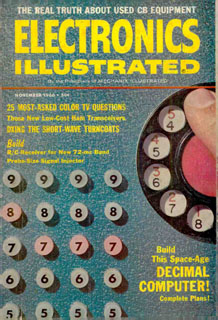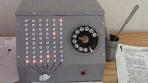
The November 1966 issue of Electronics Illustrated has a feature article, “Build This Space-Age Decimal Computer. I was inspired to make one of my own.

Despite the magazine’s hype of it being a computer, it’s really just an adding machine. But I liked its retro look and the way numbers are entered with a telephone dial.
My top priority was to make it look like the project in the magazine article. I wanted to use the same neon lamps (NE-2) and enclosure (which was not identified in the article, but turned out to be the Bud Industries C-1588).
As I researched the design described in the article, I realized it was not going to work. I remember, from my youth, hearing complaints that projects in electronics magazines did not work. I assumed it was due to errors in the article, or the fault of the person building them. But in this case, it’s simply an unreliable design.
The “computer” used ring buffers for counting. Neon lamps turn on at higher voltages than they turn off at. This allows the lamps to act as switches and memory locations. It’s possible to build a circuit, without any transistors, where a neon lamp is lit, and a pulse from the telephone dial causes it to turn off, and the next lamp to turn on.
 The problem is that NE-2 lamps are not manufactured for uniform on and off voltages. Not only are the lamps all different from each other, but their behavior changes as they age.
That means that to get a neon ring buffer to work with NE-2 lamps, you need to characterize each lamp’s behavior, group similar lamps together, and compensate for differences with resistors. After all that effort, if you get your adding machine to work, it’s still going to break after being used for a while.
Back in the ’60s, there were some neon lamps manufactured to more exacting specifications for calculating machines. But they were more expensive than NE-2s. There are even some NOS lamps available today that would work – but they’re twice the size of NE-2s. I had to choose between making my decimal computer match the original on the outside, or on the inside. I chose the outside.
(BTW, Pieter-Tjerk de Boer built an excellent Nixie clock using neon ring counters. His first attempt used NE-2 lamps. After a while, it stopped working, because the NE-2s changed as they aged. He built a new version using the more reliable MTX-90 – aka MTH-90 – lamps.)
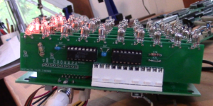
 So instead of using 1960s technology, I used 1970s technology. I used 74HC192 decade counter ICs and 74141 BCD decoders capable of driving the high voltages of neon lamps (and Nixie tubes!).
How does the article justify it’s claim that you can subtract, multiply, and divide with this adding machine? Well, subtraction is done using 9’s complement. For the others, you still need to remember your multiplication tables, and the adding machine just assists you with the adding and subtracting.
Check out the demo:
If you want to build this:
Expect the total cost of this project to be US$150 to US$200. The Bud Industries C-1588 case is the single biggest expense. The cheapest place I’ve found to get it is at Hawk Electronics. You’ll also need a telephone dial. I bought an old phone off eBay and dismantled it. Before you buy, pay attention to the dial’s appearance: the original article used a dial where the numbers are inside the finger holes. Later phone models had a plastic rim where the numbers were printed, outside the finger holes. Either will work, but I wanted to match the original project’s aesthetic.
You’ll be drilling 60 holes in steel. I started with a 1/8″ drill and gradually enlarged the hole to the final 1/4″ size. One of the PCB boards, below, is a template for the drill holes.
You’ll also be cutting an arbitrarily shaped hole to fit the telephone dial’s mechanism. I used a nibbler.
You can download my KiCad files here. There are five different boards in this project. Within each board’s subdirectory, there’s a “production” subdirectory. In there, there’s a zip file with the Gerber files. Send the zipped Gerber files to one of the many PCB manufacturers (you can do price comparisons at my other site, PCBShopper.com). The boards are:
- Power supply. It takes 120V in and outputs voltages for the lamps and logic. It’s not part of the circuit design, but I suggest you add a bleeder resistor across either of the big capacitors. Something like 100K ohms, 1/2 watt.
For the connection from the power supply to the motherboard, I’m using an old PC floppy drive power cable. I hate point-to-point wiring. - Motherboard. It provides slots for the 6 Place boards (1’s place, 10’s place, etc.). It’s also where you connect the phone dial, clear button, and rotary switch.
- “Place” boards that plug into the motherboard. You’ll need to have 6 of these made – most manufacturers will round that up to 10.
- Drill Pattern. This is just 60 holes. I taped it to the front of the enclosure and used it to drill my initial 1/8″ pilot holes.
- Rotary Switch. Remember I said I hate point-to-point wiring? So you solder the rotary switch here, then use a ribbon cable assembly to connect it to the motherboard. Also, this board acts as a template for drilling holes. You need holes in the case for both the rotary switch’s shaft and pin (to prevent the rotary switch from spinning). Use a Rotary Switch board as a template for drilling those holes. Be aware: the pin is offset 30° from the rotary switch’s leftmost position. If you’re a stickler for symmetry, you should offset the template 15° from the horizontal.
Also in the downloaded files, there’s digits.docx and 9s complement label.svg. These files contain the labels you need. I printed them out on clear adhesive inkjet paper and cut them out with an X-Acto blade.
The caps for the lamp are made by VCC. The part number is CLF_280_GLO. I purchased 60 of them here.
If you have any other questions, feel free to contact me.

I’ve seen this “computer calculator” on a magazine I found here in Italy, several years ago in a flea market…
I immediately seen the “will” in those times, to make available these machine in those years… Fantastic.
I don’t remember how many times I read this project pages, ad imagined soo if I cold do replicate it.
I’ve read also that it was *really tricky* to find two neon bulbs working at the righ voltage…
Now that you remade it in more modern electronics, I’m really tempted to replicate it.
Anyway a very good project. Thanks for sharing!